Label:Yes
The module's CE pin timing procedure can reach the 10us mentioned in the nRF24L01P technical manual, but we recommend changing it to: SPI transaction until CE goes high until the transmit interrupt is completed, then keep 1ms high time, then Lower the CE. The purpose is to switch to receive mode immediately after sending the GT-24. If CE = 0, the LNA is turned off, which will adversely affect the receiving sensitivity.
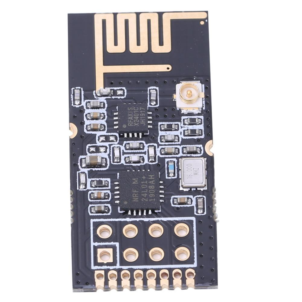
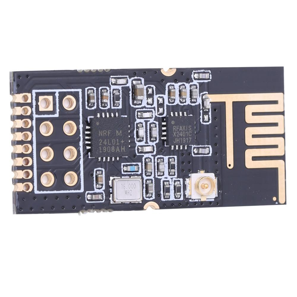
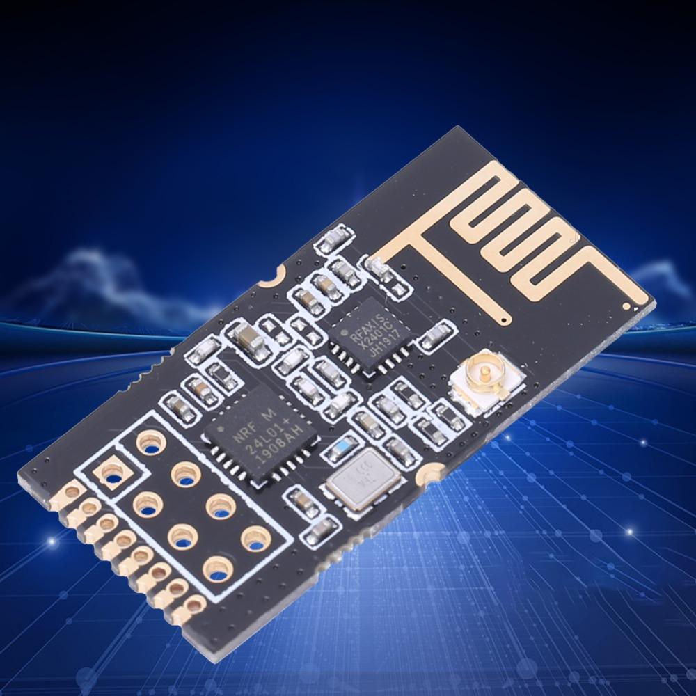
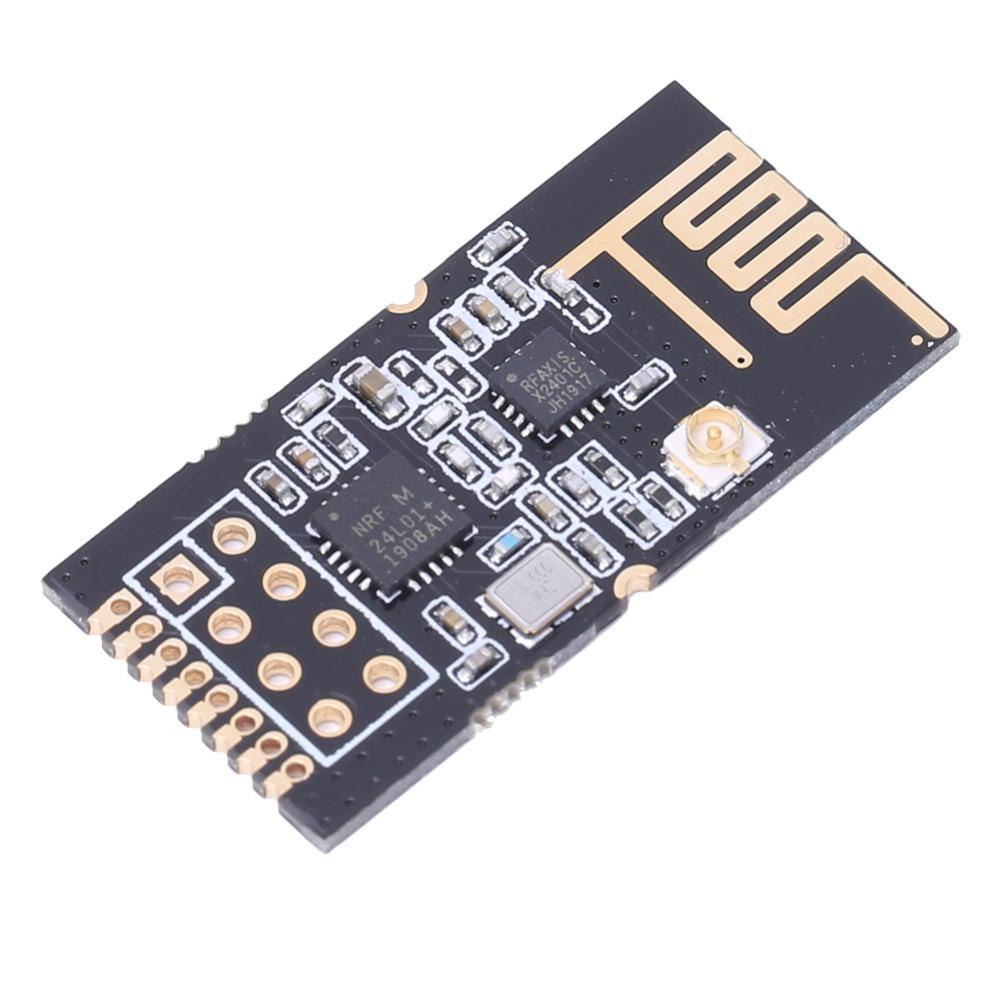
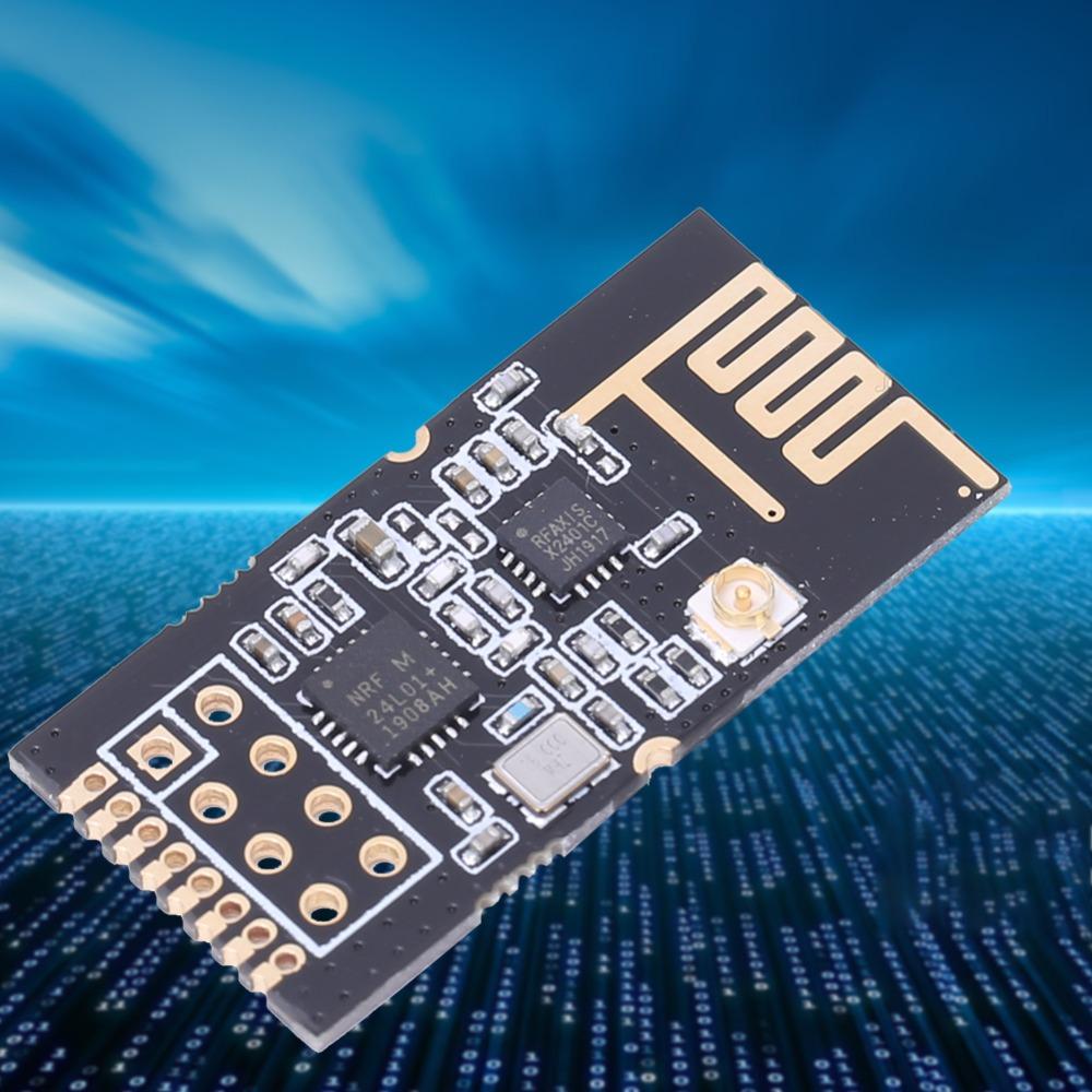
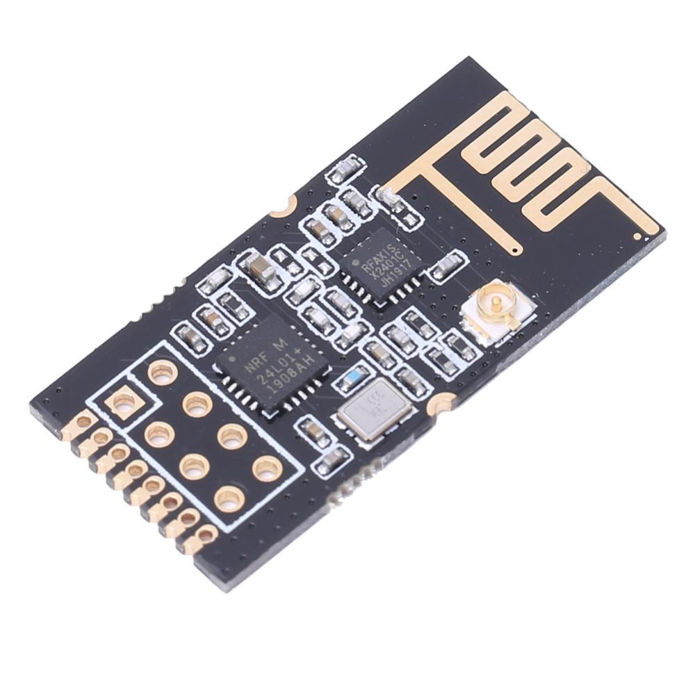
The module is nRF24L01P + PA + LNA and its driving method is exactly the same as nRF24L01P. Users can operate according to the nRF24L01P chip manual.
Support for 51 STM8S STM32 and other microcontroller development boards.
The CE pin is connected to the LNA enable pin. When CE = 1, the LNA is turned on. When CE = 0, the LNA is turned off. This function is identical to the transmit and receive modes of the nRF24L01. In other words, the user does not need to care about the functioning of the LNA at all.
The CE can be connected high for a long time, but the module must first be set to the POWER DOWN power-down mode when writing to the register. It is recommended to connect the CE to the IO port of the MCU. The IRQ can be disconnected and the interrupt status can be obtained using the SPI polling mode. However, it is recommended to use an external interrupt from the microcontroller.
Specification
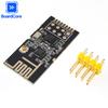
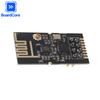
Item Type: NRF24L01+PA+LNA
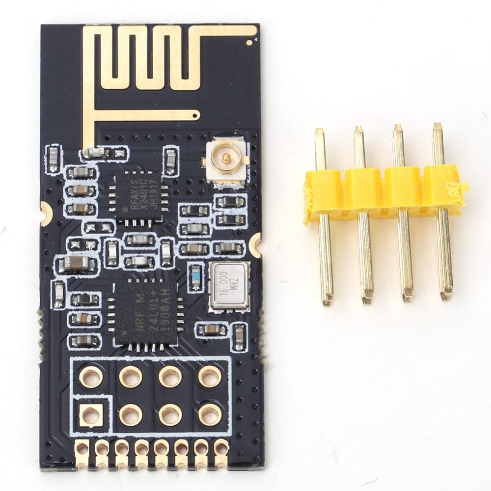
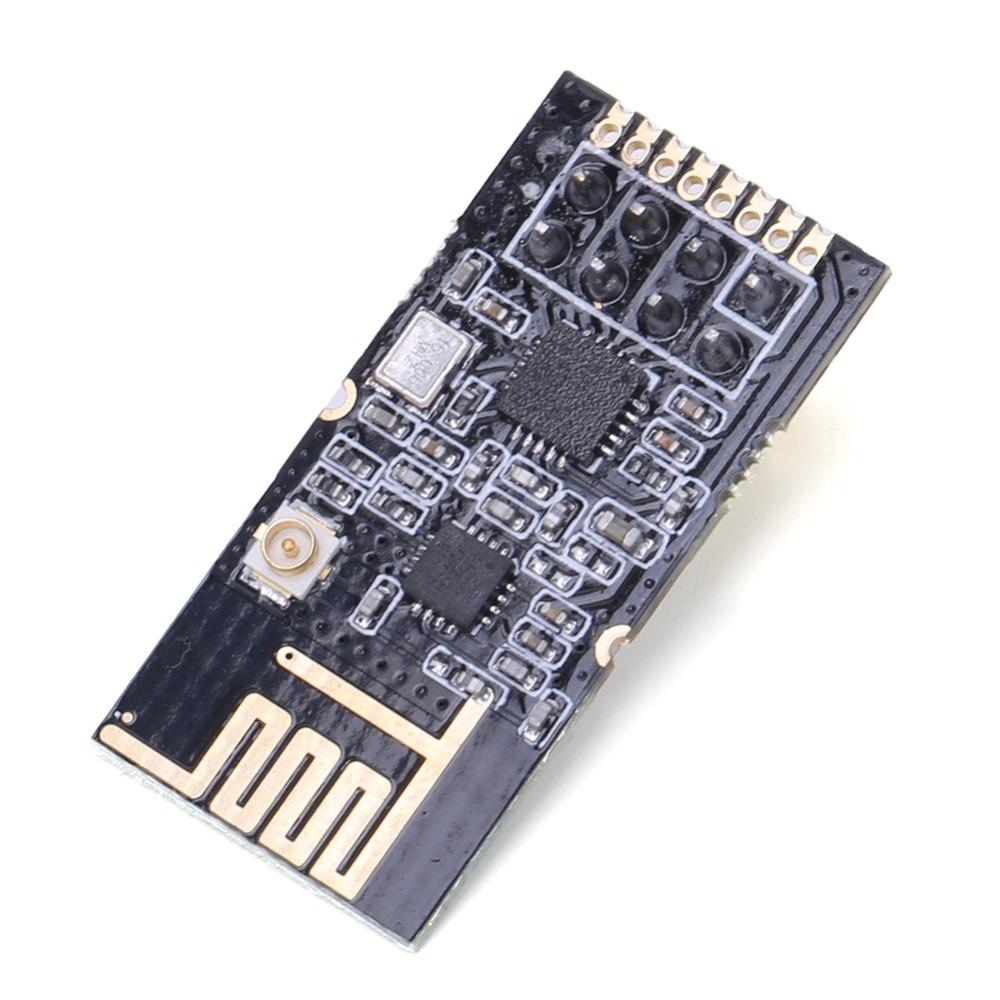
Type: Direct Insert/Patch Mounting(Optional)
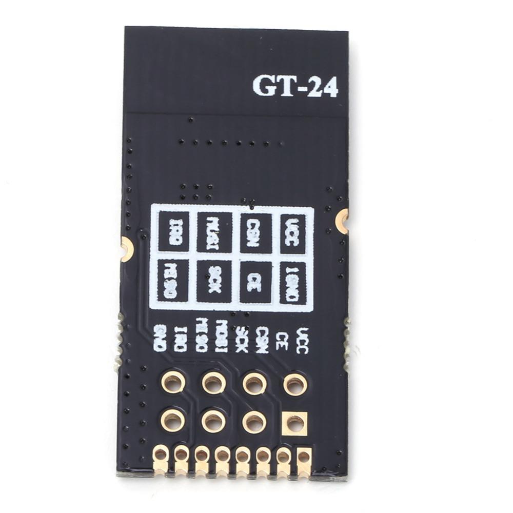
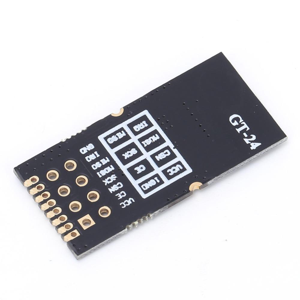
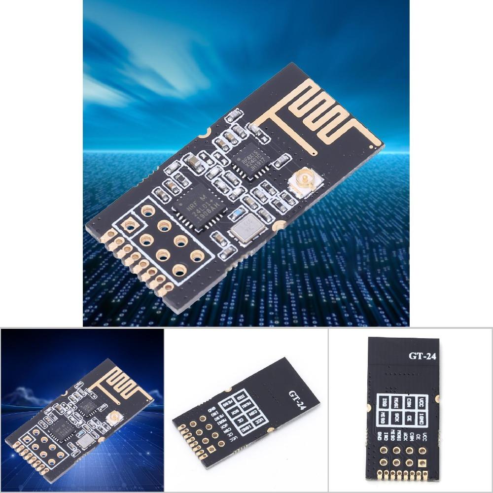
Model: GT-24
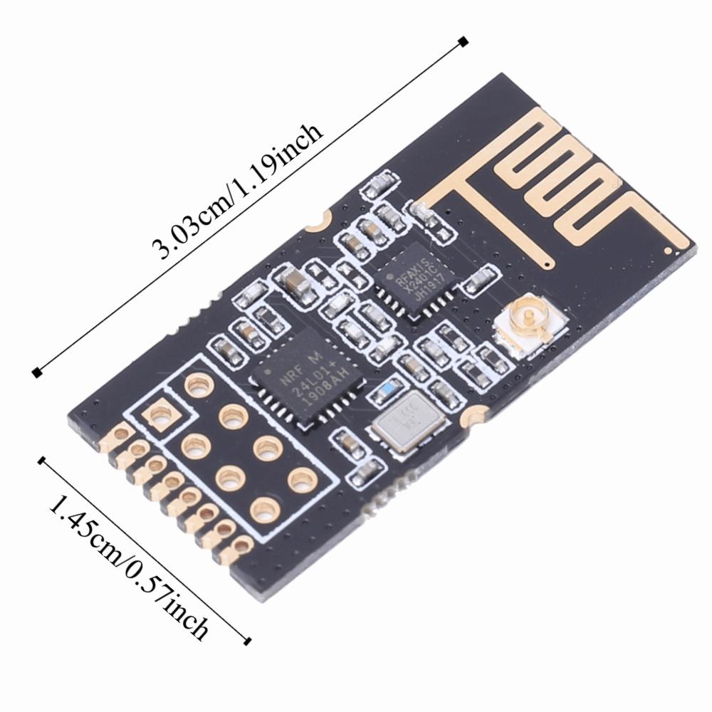
Module size : 30.3 x 14.5mm / 1.19 x 0.57in (PCB antenna included)
Color: As picture shown
Working frequency: 2.4GHz-2.525GHz (Adjustable, 1MHz step)
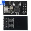
Interface mode: 1*8*1.27mm/2*4*2.54mm (The patch can also be used with the universal board and line.)
Supply voltage: DC: 2.0-3.6V (Note: Voltages above 3.6V will cause permanent damage to the module.)
Communication level: 0.7VCC-3.3V (VCC refers to the module supply voltage)
Measured distance: 1000m (Clear and empty, maximum power, height 2m, 250K air speed)
Transmit power: 4 levels adjustable up to 20dBm (About 100mW at maximum power)
Air speed : 250K-2Mbps, Level 3 adjustable (250Kbps, 1Mbps, 2Mbps)
Shutdown current: About 30uA, Test conditions: CE=0, power down mode, VCC=3.0V
Emission current: About 90mA, Power supply capacity must be greater than 250mA
Receiving current: About 20mA, CE=1
Antenna form: PCB antenna / ipex carrier antenna
Communication Interface: SPI, High speed power up to 10Mbps
Transmission length : Single packet 1-32 bytes, 3-level FIFO
Receiving length: Single packet 1-32 bytes, 3-level FIFO
RSSI support: not support, Only simple packet loss statistics are supported
Receiving sensitivity:-B2294dBm@250Kbp
Operating temperature: -40~+85°C, Industrial grade
Working humidity: 10%-90%, Relative humidity, no condensation
Storage temperature: -40~+125°C
Package List(for Direct Insert Type)
1 x Module
Package List(for Patch Mounting Type)
1 x Module
1 x Pin Header
Note
Notice the grounding is good, the paving area is large, and the power supply fluctuation is small. The filter capacitor should be added as close as possible to the VCC and GND pins of the module.


 Rückerstattung bei Nichtlieferung